Here's a two dimensional diagram of a rigid frame, the simplest type to build:
Parts Of The Frame - Orientation:

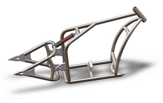
The parts made of tubing that make up the special shape of each bike are:
- The Wishbone Tubes that run along the top and the back of the bike. These two tubes are bent to make space for the seat. They get welded together and then to the top tube at one end and the bottom rails. (This is on a rigid frame - on a swing arm you weld them to the 'side plates'.) When the two pieces that make up the wishbone tubes are welded together they are shaped like a wishbone.
- The Top Tube or Backbone runs from the wishbone tubes to the neck stem, and is welded to both.
- The pair of Bottom Rails have the most serious bending and are welded to the neck stem at the front and the wishbone tubes at the rear (or side plates if you are building a swingarm frame).The Downtubes are just one part of the bottom rails; the section that comes between the neck stem and the first big bend.
- The Center Post or Seat Post is just a tube welded to the backbone and a crossbrace that runs between the two bottom rails (see the overhead few further on). It's there to make the frame more rigid, and it's worth noting that not all designs include one. If this is the case they clearly need to gain extra rigidity from else where.
This is our frame from above - the wishbone shape is very obvious now, and it's easy to see how the steering is attached:
Wishbone Shape Of The Frame:

There are usually three parts around the neck. The Neck Stem is the tube where the frame connects to the forks. It's machined steel, and will be fitted with bearings of some kind so it can support the front end of the bike. Because it has this vital role, there are two further parts that help out by adding strength.
The Neck Gusset Tube is a tube welded to both the backbone and the bottom rails. The Neck Gusset is a flat piece of steel that connects all of this together, again adding strength. The neck gusset is usually welded to everything in sight - the backbone, neck stem, neck gusset tube and the bottom rails.
The Neck Gusset Tube is a tube welded to both the backbone and the bottom rails. The Neck Gusset is a flat piece of steel that connects all of this together, again adding strength. The neck gusset is usually welded to everything in sight - the backbone, neck stem, neck gusset tube and the bottom rails.
There are many variations on this theme; many frames have no gusset but do have struts between the downtube and the neck stem, for example.
Here is a little diagram to show the gusset welds:
Detail Of The Neck Gusset and Neck Gusset Tube:

That's it for the basics of the frame. Now we need to think about how we're going to secure the engine, transmission, rear wheel and gas tank to the frame. When we plan and build the frame, we need to put thought into these few other essentials, known collectively as the mountings.
Chopper Frame Mountings:

Mounting essentials for securing the engine, transmission, rear wheel and gas tank to the frame:
- Top Mount Bracket
- Motor Mounting Plates
- The Forward Control Adapters
- Transmission Plate
- Seat Clip
The engine is fastened in place by the Top Motor Mount Bracket or Engine Mount, a heavy steel bracket which is welded to the backbone (in the diagram above it is roughly halfway between the tank clips and the seat clips, hanging down with a bolt hole drilled in it), and the by two Motor Mounting Plates or Engine Mounts on which the motor will sit. All three are labeled engine mounts in the illustration.
The motor is bolted to these mounting plates (there is a standard engine bolting pattern) so the engine is secured at three separate points, one or two of which are large machined, pre-drilled, steel plates. It's cheap and easy to buy the motor mounting plates to suit the engine you choose.
The Forward Control Adaptors are threaded lugs to which the forward controls will be fitted. They sit by the forward motor mounting.
The Forward Control Adaptors are threaded lugs to which the forward controls will be fitted. They sit by the forward motor mounting.
The gas tank is held by the well named Gas Tank Mounting and Tank Clips- on the illustration below I've only shown the tank clips, because most often the mounting is fabricated using the gas tank as a guide later on in the assembly.
It's usually a small flat plate that matches the bolt holes in the tank which is welded to a mitered tube that you measure in-situ, and this is then welded to the frame. This way the gas tank fits snugly and can be removed by using the bolts. The tank clips that are shown sit between the two halves of the assembled tank, in the ridge that runs through the center at the bottom of the tank.
Towards the back of the bottom rails, behind the center post, we mount the Transmission Plate, and bolt the transmission to it. The plate itself can be welded to the frame, or bolted, and again can easily be bought ready machined for your choice of transmission.
Finally there needs to be a Seat Clip which will be fixed to the top of the wishbone tubes somewhere in front of the center post, and onto which the seat clips. Obviously you need to know what seat you're going to be using before fitting this, and it can be left until late on (but usually before painting).
A Word About Swingarms.
Hardtail: | Softail: |

The frame on the left is our Sportster style hardtail frame 250 millimeter. The frame on the right is our specially designed softail (swingarm) bobber style frame 200 millimeter.
Here we're concentrating on rigid chopper frames, but it is possible to build a swingarm frame.
The swingarm is the rear portion of the frame and is used to hold the rear wheel in place and allow for movement as part of the rear suspension system. It's attached to the frame on a pivot axle and needs a suspension system bolted between the frame and swingarm to limit the movement of the swingarm. Swingarms can be bought made up, in which case you can fabricate a frame to fit it.
Such a frame will look similar to those above but will not extend to the rear axle, but rather will have a half diamond shape rear portion to accommodate the diamond shaped swing arm section.
Frame Geometry:
Here we discuss frame geometry; an important area to be familiar with as you learn how to build a chopper frame.
In all Cruisers, the foot pegs and shifter are located a long way forward so your legs can stretch out. On a well designed bike, this is a comfortable riding position - Cruisers make good touring bikes because of this feature combined with their stability at high speeds.
In all Cruisers, the foot pegs and shifter are located a long way forward so your legs can stretch out. On a well designed bike, this is a comfortable riding position - Cruisers make good touring bikes because of this feature combined with their stability at high speeds.
A badly designed Cruiser drops all your weight onto your Coccyx (tailbone) and is a far from comfortable ride. The placement and shape of the handlebars stretch the arms out and add to the laid back style. Choppers are an extreme, stripped down variation of the Cruiser, with larger front fork rake and banana seats. Choppers carry a V-twin engine, usually a big one.
The frame geometry is how this look and style is achieved. Here's the frame diagram again:
The frame geometry is how this look and style is achieved. Here's the frame diagram again:
A Chopper Frame Without Mountings:

Different choppers looks are achieved by changing the length of parts of a standard frame. It's what's known as stretching. Extend the downtube for example and you can get a more obtuse angle for the forks and a longer overall bike (the front wheel moves further away from the frame). It's done for looks, for a better fit for a particular rider, or to change the way the bike handles.
It isn't done by just welding an extra few inches into the frame where you want to stretch it, but is done at the time of building the frame, with all the angles and lengths carefully worked out.
To understand this frame geometry section easily, I suggest getting some paper and a pen and doing some drawing of your own. By the end of this section, you'll be able to design the chopper of a stickman's dreams!
Stretching takes place in these three main areas -
Stretching takes place in these three main areas -
- In the rear by extending the wishbones and bottom rails
- Up by the neck by extending the top tube and in the downtubes to shift the angle of the neck.
This frame geometry diagram shows where I mean:
Where The Stretch Takes Place:

Stretching The Rear:
This is what happens when you make a rear stretch. The axle has effectively moved up, lowering the bike:

Next in our chopper frame geometry section is a stretch in the front end. In this case a combination of two of the stretches I mentioned above. In this case the effect has been to lengthen the bike without altering the rake.
If just the bottom tube had been extended then the rake would have grown (see below for the full explanation of rake!):
Stretching Forward By Extending The Backbone:

Frame Geometry Conclusion:
With your pen and paper you can draw entire bikes to see what happens to the frame and the rest of angle of the ride and forks, the height of the ride from the ground and so on. To understand the change in handling characteristics that result from stretching the frame, we need to look at rake and trail.
Understanding Rake and Trail!
30 Degree Rake:
Rake is simply the angle formed by a line through the neck stem with a vertical line drawn to the ground when the bike is standing. It looks like this:

40 Degree Rake:
As you know, choppers have a larger rake angle that most other motorbikes:

Zero Rake?
A zero rake is when the neck points straight at the ground, and you never see it in a bike. You would have something impossible to handle - a clown's unicycle and a shopping cart both have zero rake.
Generally, speaking machines with larger rakes will be great for stability and going in a straight line, but less good for tight maneuvers than those bikes with smaller rakes.
This is simply because increasing the rake moves the front wheel further away from the rest of the bike, increasing the overall length and therefore the turning circle. So a large rake usually means the bike is good for cruising on the highway. A sport bike may have a rake of 24 degrees, a cruiser 32 degrees, with ten to fifteen inches difference in their wheelbase dimensions. Each is designed for a different purpose.
Trail is a relationship between the front wheel axis and the steering axis, measured as shown in the diagram below. It's measured in inches, and you can easily measure it yourself with a tape measure and a stick.
A Diagram Illustrating Trail:

Most bikes have a trail between 2 and 4.5 inches. It can be altered by changing the neck rake, the fork length and type, triple trees, and the wheel diameter.
This is not a hard a fast cut-off point and good bikes can be built with trails either side of the normal range, including a zero trail. If we go much larger than five inches or so we would get a bike that's really stable at speed, probably handling sluggishly, and which at low speed is going to be difficult to keep in line.
It is possible to end up with negative trail (where the wheel axis is behind the steering axis) if you use some kind of extension at the bottom of the neck to force out the forks without doing any frame alterations - triple trees that do this are available.
It is possible to end up with negative trail (where the wheel axis is behind the steering axis) if you use some kind of extension at the bottom of the neck to force out the forks without doing any frame alterations - triple trees that do this are available.
Everyone agrees that this is dangerous however, since the machine may handle in unpredictable ways at speed and on corners, which is never a good idea. Out of interest, it looks like this:
A Diagram Showing Negative Trail (Bad)!

How To Build A Chopper Frame:
The Raw Materials You'll Need!

The main frame component is tubing. Tubing is measured by it’s size on the outside, so 1.25 inch tubing has an outer diameter of 1.25. Piping on the other hand, used for plumbing, is measured by the inside size so 1.25 inch piece of pipe would be fatter than similarly labeled tubing. Frames can be made of piping, but it’s very bad.
They are going to end up very heavy and quite simply the material is wrong for the job. Don’t confuse massive weight with strength - you should be able to carry the frame reasonably easily when you’ve finished it because t should weigh about 40 pounds.
No comments:
Post a Comment